Index of subjects
- Program a neuron in Python
- Program the nandneuron as a Python function
- Program the nandneuron as a Java class
- Program a one bit binary number adder using the nand function
- Program a two bit binary number adder using the nand function
- Program a 2 layer neural sigmoid network in Python
- Program a 3 layer neural sigmoid network in Python
- NEW: Reinforcement learning - into robotics
- Question? Contact me!
Neural networks, Machine learning, Reinforcement learning
New2022: For now i left the Raspi approach and completed a little OTTO robot with a tiny ANN for Arduino nano! It works!
Follow me on this adventure.
There are two domains of AI, the assisted learning (the neural networks below, or ANN) and the non-supervised learning.
For the Raspi I AM USING WINDOWS 10, PYTHON VERSION 3.6 and 3.7 WITH NUMPY; SO THATS WHAT YOU NEED (SEE WWW.PYTHON.ORG). Easy to install.
LINUX (UBUNTU) WILL WORK AS WELL IF NOT BETTER, BUT I HAVE CHOSEN WINDOWS 10 FOR PRACTICAL REASONS -
Raspberry Pi comes with its own very complete Python package on the Raspberry (Debian) OS.
NEW:
I HAVE CHANGED TACK. A NEURAL NET ON DE PI ZERO IS JUST A BIT TOO MUCH FOR IMAGE RECOGNITION .
FOUND AN IMPLEMENTATION OF A SMALL (3X5X4) ANN ON ARDUINO. THE FUNNY OTTO DIY WALKING ROBOT IS DRIVEN BY ARDUINO NANO, AND
THIS ACTUALLT WORKS. SEE BELOW.
(PICS AND SOURCE CODE WILL FOLLOW)

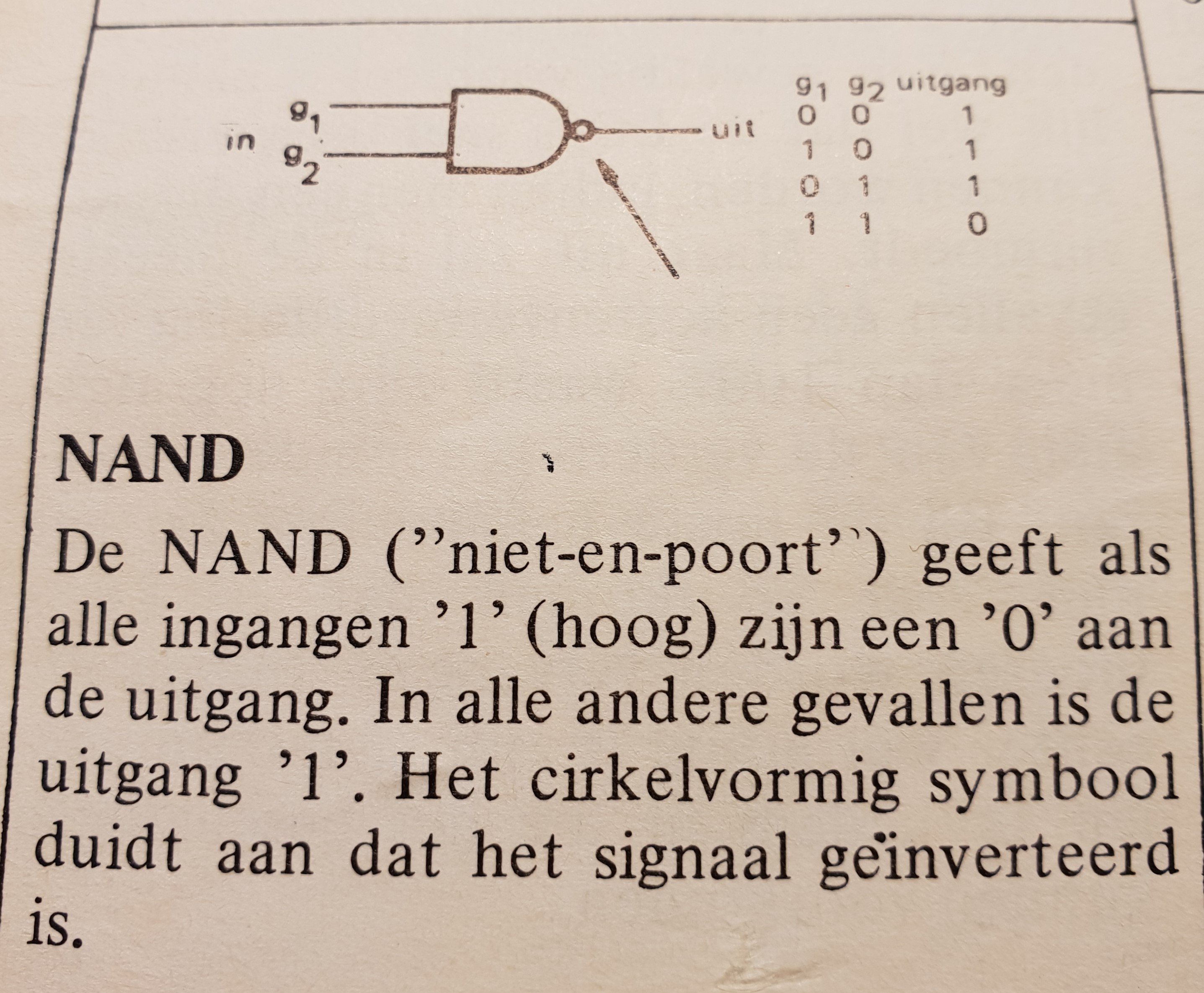
The mythical NAND gate as illustration of a neuron
The NAND gate is an interesting starting point and easy to use as simple exercise to emulate a single artificial neuron. It doesnt learn yet, but shows the internal neuron workings with simple firing mechanism..
Also the NABD is the universal building block of THE computer as we know them.
Available as simple electronic integrated circuits, with 4 and more gates on a chip (you can buy them cheaply, for example the TI 7401 chips).
A NAND (NOT-AND) gate (the chip) will output a ONE (5 volts) only if both inputs are ZERO (zero Volts).
Look it up; there are also AND, OR, XOR and NOT gates, doing other things with ones and zeros.
With multiple NAND gates we can perform binary additions, compare binary numbers, and make flipflops as memory cells and thus registers.
The building blocks of a computer are memory, registers, arithmetic units (AU), comparators, counters that can all be constructed with NAND gates., therefore a computer can be constructed using NAND gates.
You would need a lot of them but its definitely doable and it has actually been done. If you think of the early beginnings of computerchips, INTEL's 4004, a similar 4-bit CPU is certainly doable with NAND gates.
If you are interested Google the 7401 TI chips, containing 4 nand gates in silicon, 14PIN DIL, still generally available., cheap.
An artifical software Perceptron/neuron with two inputs.
-
This is to get into some of the very basic basics to get you started with the AI concepts as well as with Python to play around with, before we get into the real thing.
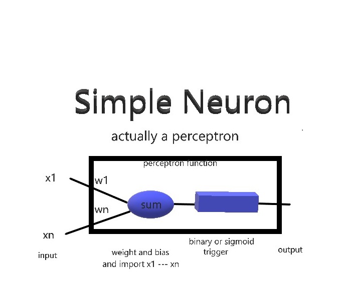
A neuron (or perceptron) will take inputs and produce a particular output. This happens all the time in your brain, but here we will create the software model of a neuron/perceptron.
By applying WEIGHTS to the inputs, we can make a particular input more or less important than another; and by adding a socalled BIAS (number) we can make the neuron easier or less easy to trigger.. Other neurons may have a different bias and there be more or less difficult to trigger.
After some summing and multiplying the inputs and weights we will apply a TRIGGER (also called ACTIVATION FUNCTION) to the result , being the function that lets the neuron fire or remain quiet.
(important summary) The functions of the perceptron are thus:
- Input the x1 ----- xn values (variables or array)
- Do the summing algorithm with weights w1 --- wn and bias b: w1 * x1 + w2 * x2 + wn * xn + b
- Perform the trigger or activation function on the result of the sum
- Output the end result to the world
At this stage we do a simple binary activation (or trigger) , if the resulting sum is <=0 then the output becomes 0, else if the sum > 0, the output = 1 (variables or array).
In the python script in this chapter, the values of weight and bias are not preset, so you still can play around with various values !!!
X1 to Xn are the input values, and output is the value we are trying to achieve, using the weight and bias. Here we use only two inputs, x1 and x2. Start with bias 3, weights -2 and two inputs, x1 and x2 (use 1 or 0). These values will let the neuron behave as NAND. Lateron we will see that the LEARNING process consists of adjustting weights and biases so that the required output is achieved .
In Python speak this becomes:
print ("defining a perceptron")
x1 = int (input("number x1: "))
x2 = int(input("number x2: "))
w1 = int(input("number weight 1: "))
w2 = int(input("number weight 2: "))
b = int(input("number for bias: "))
output = (x1*w1)+(x2*w2)+b
if (output > 0):
output =1
else:
output = 0
print (output)
You can paste the above into Idle (the Python shell / editor), save it with a .py extension in the directory where Python.exe lives and run it under python.
Better practice is to add python.exe location to the path variable, system environment variables. It allows you to run the python commands from within any folder in your system (and you avoid cluttering up the folder with python. exe etc.). I havent done that - yet. Ask me if you dont know how to do the system path.
(Alarm!) Python can get very angry if you misuse indenting ; and dont forget brackets, semicolons etc!
By all means try out various weights and biases; nothing gets damaged, except your ego perhaps.
Use 0 or 1 for the inputs, we are still talking binary.
Here a screenshot of what actually happens.
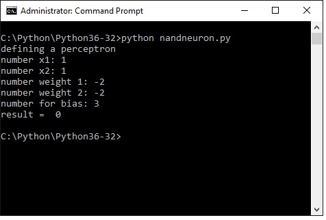
As expected with x1 and x2 being 1, the result is 0, thats what a NAND gate does.
Try some other x1, x2 . weight and bias input values. Just to pass the time.
Note: these are the principles. You can skip all the stuff about NAND gates and go to the neural networks directly.
NAND gates are my personal hangup as an old hand at computer technology.
Perceptron/neuron weighted (hardcoded) to function as NAND gate, defined as Python function:
This is the same program as the previous chapter, but as we want to repeatedly use the NAND gate in the next chapters, its useful to define it as a Python function.
A function can be called repeatedly with input parameters., instead of retyping the same code all the time.
For our purpose this particular perceptron is parameterized (hard coded) to work as a NAND gate, now with only x1 and x2 as variable input.
Copy the program lines below into IDLE (the handy Python shell), save as e.g. nandfunction.py or some name you fancy, in the folder where python.exe lives , start the windows command-shell, cd to that folder and run it.
Now do it:
def nand (x1, x2):
print ("defining a perceptron NAND as function")
# ("NAND defined by weights -2 and bias 3")
w1 = int(-2)
w2 = int(-2)
b = int(3)
output = (x1*w1) + (x2*w2) + b
if (output > 0):
output =1
else: output = 0 return output print ("nand is now a function") x1= int(input("number 1 or 0: ")) x2= int(input("number 1 or 0: ")) print ("Öutput NAND is: ", nand(x1,x2)) This is the result in the command shell: 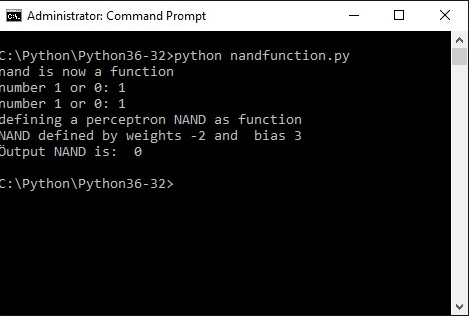
Perceptron/neuron hardcoded as a Java class:
WTH, Just for the fun of it i downloaded Java SDK and tried my hand at the previous NAND routine , now as a Java class (actually two classes).
These are my first stumblings in Java, so there are very probably better ways to do things. I adapted listings from the book " Java for dummies" , by adapting and changing existing listings you start to understand whats happening.
OOP is a totally different way of thinking for me and the program may still be a bit awkward. I am trying to wrap my brains around the question what the benefit is of the class/object Java approach in comparison with the Python function approach, or as I wrote back in the seventies in machine assembler language a main program with a huge amount of subroutines and interrupt handling routines.
I use Wordpad to edit the source. An IDE may be better as it can prevent you making some standard errors. At this stage i prefer the direct approach of a wordpad file - if you make an error the program will not compile. Straight text input is totally unforgiving.
The program consists of two Java classes, Neuron and UseNeuron
You must save the two wordpad files with these names (icluding capitals) and the extension .java
The Neuron class defines a generic two input, one output logical gate (can be anything, NAND, AND, OR, whatever)
The UseNeuron class defines a NAND object, gets (called the method) the input values and produces the result with a very simple activation. Try to understand, there is a lot of tutorial info on the net.
UseNeuron also defines an AND object for illustration, which i will not use.
For java i have set the system environment path to point a the java executables, so i can run the jave programs from the folder where they live (a bit cleaner than what i did with Python)
So create and save your .java wordpad files,
Then run :
javac Neuron.java
this will compile into a file Neuron.class
and run:
java Neuron
this will do nothing visible as it only establishes the class Neuron
then run:
javac UseNeuron.java
which compiles into a class file UseNeuron.class
and run:
java UseNeuron
which will get x1 and x2 inputs and produce the NAND value
The Neuron.java class source:
public class Neuron {
/* This is java neuron devinition modelled after 7.1
* only defines the class Neuron
* x1 and x2 are the two inputs
* output is the output after activation
*/
double x1;
double x2;
double output;
}
And the UseNeuron.java class source:
import static java.lang.System.out;
import static java.lang.System.in;
import java.util.Scanner;
public class UseNeuron {
/* This class is based on java for dummies listing 7.2 */
/* implements object Nand neuron using class Neuron */
public static void main(String args[]) {
Neuron nandNeuron;
Neuron andNeuron;
/* only using the nand */
nandNeuron = new Neuron();
andNeuron = new Neuron();
/* nandNeuron.x1 = System.in.read(); */
/* further study, why i cant use nandNeuron.x1 */
/* directly with system.in or scanner */
/* here obtain the input values x1 and x2 */
Scanner scanner = new Scanner(System.in);
System.out.print("Enter your x1: ");
int x1 = scanner.nextInt();
out.print(x1);
out.println();
System.out.print("Enter your x2: ");
int x2 = scanner.nextInt();
out.print(x2);
out.println();
/* here the neuron function using */
/* fixed weights and bias */
nandNeuron.x1 = x1;
nandNeuron.x2 = x2;
nandNeuron.output = 1;
nandNeuron.output = (nandNeuron.x1 * -2)+ (nandNeuron.x2 * -2) + 3;
out.println();
/* here the very simple activation function */
/* just determining 0 or 1 */
if (nandNeuron.output > 0) {
nandNeuron.output =1; } else {
nandNeuron.output=0; }
/* and display the result */
out.print("The NAND function: ");
out.print(nandNeuron.x1+ " NAND "+nandNeuron.x2+" gives: ");
out.print(nandNeuron.output);
}
}
The result in the command shell, two ones give one zero, as expected.
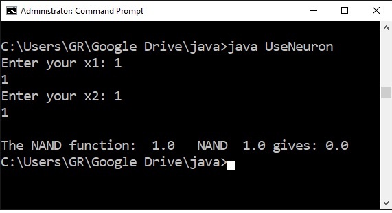
Try the whole NAND truthtable to see if it works.
It does.
Now a program using the NAND neural function to emulate a 1 bit binary adder:
If you have seen enough of the NAND gates, you may skip to the Neural Network section - the real thing,
The previous chapter was just about one simple single nand gate.
Next step is to implement a binary adder for two one bit numbers plus a carry from a previous adder.
You need 4 nand perceptrons for addition and 1 nand perceptron for the carry bit.
The output is 2 bits, 1 bit sum plus 1 bit carry.
The binary truth table for this is then:
0 + 0 = 0 carry 0 result shows as 0 0 (decimal 0)
0 + 1 = 1 carry 0 result shows as 0 1 (decimal 1)
1 + 1 = 0 carry 1 result shows as 1 0 (decimal 2)
If there was a carry from a previous stage the end- result for 1+1 would be 11 (3) .
Without further ado I have defined the add1bit as a function, which calls the nand function multiple times.
The program structure is simple; a. define the nand function, b. define an add1bit function, then c. (main) the code lines to input the values you want to add and run the add1bit function, which will run de nand function, then d. output the result. The lines under c. are called ' main' in other languages like C , Pascal., Java
The program lines are copied directly from IDLE, you can copy/paste back through IDLE or paste directly in a wordpad file and save with extension .py.
Save in the location where python exe lives and run through the Windows command shell. For Linux the principle is the same.
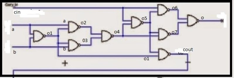
The variables o1 upto o7, cin, cout and o refer to the nandgates (ie neurons!) in the diagram, so you can see what happens.
# using the nand function 5 times to create a AU
# adding two one bit binary numbers, carry in and carry out
def nand (a, b):
w1 = int(-2)
w2 = int(-2)
bias = int(3)
out = (a*w1) + (b*w2) + bias if (out > 0):
out =1
else:
out = 0
return out
def add1bit (a, b, cin):
o1 = nand(a,b)
o2 = nand(a,o1)
o3 = nand(b, o1)
o4 = nand(o2, o3)
o5 = nand(cin, o4)
o6 = nand(cin, o5)
o7 = nand(o4,o5)
o = nand(o6,o7)
cout = nand(o1,o5)
return cout, o
#input binary numbers to be added
print ("Enter two 1-bit binary numbers")
a0 = int(input("number 1 or 0: "))
b0 = int(input("number 1 or 0: "))
cin = int(input("carry in, number 1 or 0: "))
# now add m up
result = add1bit (a0, b0, cin) print ("Result now is carry - sum: " , result) Here the screendump of the process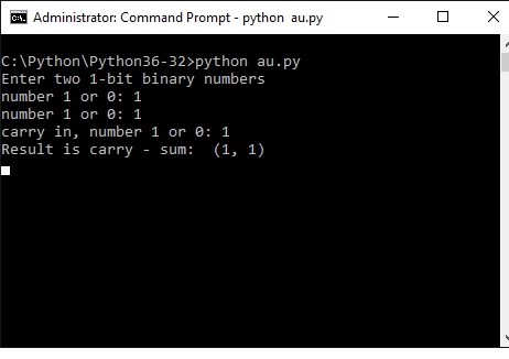
Adding two two-bit binary numbers
I got carried away slightly, so skip to the neural network chapters you have had enough.
The diagram below is actually a 4-bit adder. As we are doing this as exercise we only implement a two two-bit number adder Python. Doing a full 4-bit adder is just more of the same.
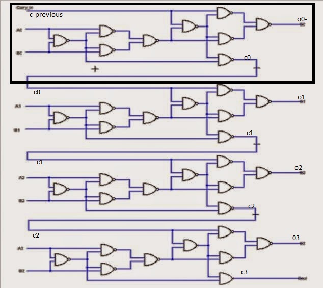
This is the embryonic beginning of a real computer
An AU (arithmetic unit) is used for several purposes, such as adding numbers or function as the program counter (points to the address of the next instruction to be fetched from memory and executed).
Once this is done, adding 4 or 8 bit numbers is just more of the same (wont do that here, promise).
The truth table for addition of two two-bit numbers is:
00 + 00 = 00
01 + 00 = 01
01 + 01 = 10
10 + 01 = 11
10 + 10 = 00 plus carry 1 (100)
11 + 01 = 00 plus carry 1 (100)
11 + 10 = 01 plus carry 1 (101)
11+ 11 = 10 plus carry 1 (110)
Output is 2 bits plus carry
Values change when the input carry of a previous stage is true. We use the nand function defined above again as building block.
Here in python speak:
# a multi bit binary number adder using the nand function as basic block
# each two bit plus carry adder will be used as a function
# numbers represented by a1 a0 and b1 b0 , c is carry
def nand (a, b):
w1 = int(-2)
w2 = int(-2)
bias = int(3)
out = (a*w1) + (b*w2) + bias
if (out > 0):
out =1
else:
out = 0
return out
def add1bit (a, b, cin):
o1 = nand(a,b)
o2 = nand(a,o1)
o3 = nand(b, o1)
o4 = nand(o2, o3)
o5 = nand(cin, o4)
o6 = nand(cin, o5)
o7 = nand(o4,o5)
o = nand(o6,o7)
cout = nand(o1,o5)
return cout, o
def add2bits (a1, a0, b1, b0, cin):
a=a0
b=b0
cout,
o0 = add1bit(a0,b0,cin)
cin = cout
a = a1
b = b1
cout, o1 = add1bit (a1,b1,cin)
return o1, o0, cout
#input binary numbers to be added
print ("Enter two 2-bit binary numbers")
a1 = int(input("a1 number 1 or 0: "))
a0 = int(input("a0 number 1 or 0: "))
b1 = int(input("b1 number 1 or 0: "))
b0 = int(input("b0 number 1 or 0: "))
cin = int(input("carry in, number 1 or 0: "))
cout = 0
# now add m up
result = add2bits (a1,a0, b1, b0, cin)
bit1, bit0, carry= add2bits (a1, a0, b1, b0, cin)
print ("carry: -", carry, "bit1: -", bit1, "bit0: -" , bit0 )
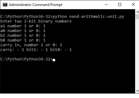
Below you see what happens in the command shell.
The result shows binary 111, which is decimal 7, as we added 11 (3) + 11 (3) + 1 = 111 (7)
Basic terminology: Sigmoid neurons, first derivative and matrix multiplication - dont panic.
YOU CAN SKIP THIS SECTION AND COME BACK WHEN YOU THINK, OY, WHATSTHIS?!
Some mathematical shit here which is good to have heard of. (Python will take care of the difficult internals).
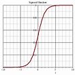
The issue with the activiation function sofar is that it flips between 0 and 1 and could become unstable.
The difference between perceptrons and sigmoid neurons is that sigmoid neurons don't just output 1 or 0. They can have as output any real number between -1 and 1, so values such as 0,486654 and 0,9988321 are legitimate outputs - as we will see later.
The sigmoid function is available in Python (numpy toolset).
In python speak . If you use the ' as' option you can call numpy by using 'np', a lot shorter. Like this:
import numpy as np
def sigmoid(z):
return 1.0/(1.0+np.exp(-z)):
I dont go into the deep with eulers number and more like that. Look it up, lots of stuff on the internet.
In order to play around with AI you only have to know how to import numpy and how to call the function.
Rather than a very steep transition between 0 and 1 , the sigmoid will give a sliding (non-linear) scale of numbers, for example:
Derivative
one more important concept you have to be aware of, is the derivative (in dutch afgeleide). Sorry about that.
You only have to be aware what is use is., understanding is another matter.
The first derivative of a function will give the tangent line tilt at particular point of the original function. If the derivative is negative the tilt is to the left, else to the right, thats it. You can also determine how steep the curve is at that particular point of the graph.
It is used to check whether we should adjust parameters forward or backward when training a neural network. This is an over simplification, so by all means check on the web.
Matrices and multiplying matrices
In the NAND gate examples i coded each neuron as a function.
In Neural Networks a more efficient way is to use matrix and matrix multiplication.
Neurons and synapses (the weights) in a network are represented by matrices - for our purpose here matrices are stored in numpy arrays, and the multimplication etc. is done in one feel sweep for all neurons using numpy dot multiplication of arrays (= matrices). There is a load of stuff on the internet on the subject, but here a small summary fo you can understand the code lines following.
array1([
[0, 0, 1],
[0, 1, 1],
[1, 0, 1],
[1, 1, 1]])
This is a matrix 4 x 3, ie 4 rows 3 columnsarray2([
[2],
[2],
[2]])
This is a matrix 3 x 1 ie 3 rows 1 column
When we multiply these two matrices the result will be array3;
Array3([
[2],
[4],
[4],
[6]])
Multiply gives matrix 4 x 1 ie 4 rows 1 column
The rule in general is :
· The number of columns of the 1st matrix must equal the number of rows of the 2nd matrix.
· And the result will have the same number of rows as the 1st matrix, and the same number of columns as the 2nd matrix.
Dont worry too much. Its nice if you can understand it, numpy will solve the whole thing for you - and fast.
A 2 layer artificial neural network (ANN) to play with
I first have to apologize to all those clever people (Phd, professors and the like) who also have published on this subject. I've reused (uh, loaned?) ideas and Python solutions and after a good deal of mixing and shuffling came up with the easy examples below.
I hope I added some value to place it in the context and sequences of this uhh, tutorial and make it accessible to morons like myself.
What i also noticed is that there is a naming convention issue here; you will see a 2-layer neural network also referred to as a single layer. I see a network as multiple connected things, so a minimum useful network wil consist of TWO LAYERS OF NEURONS.
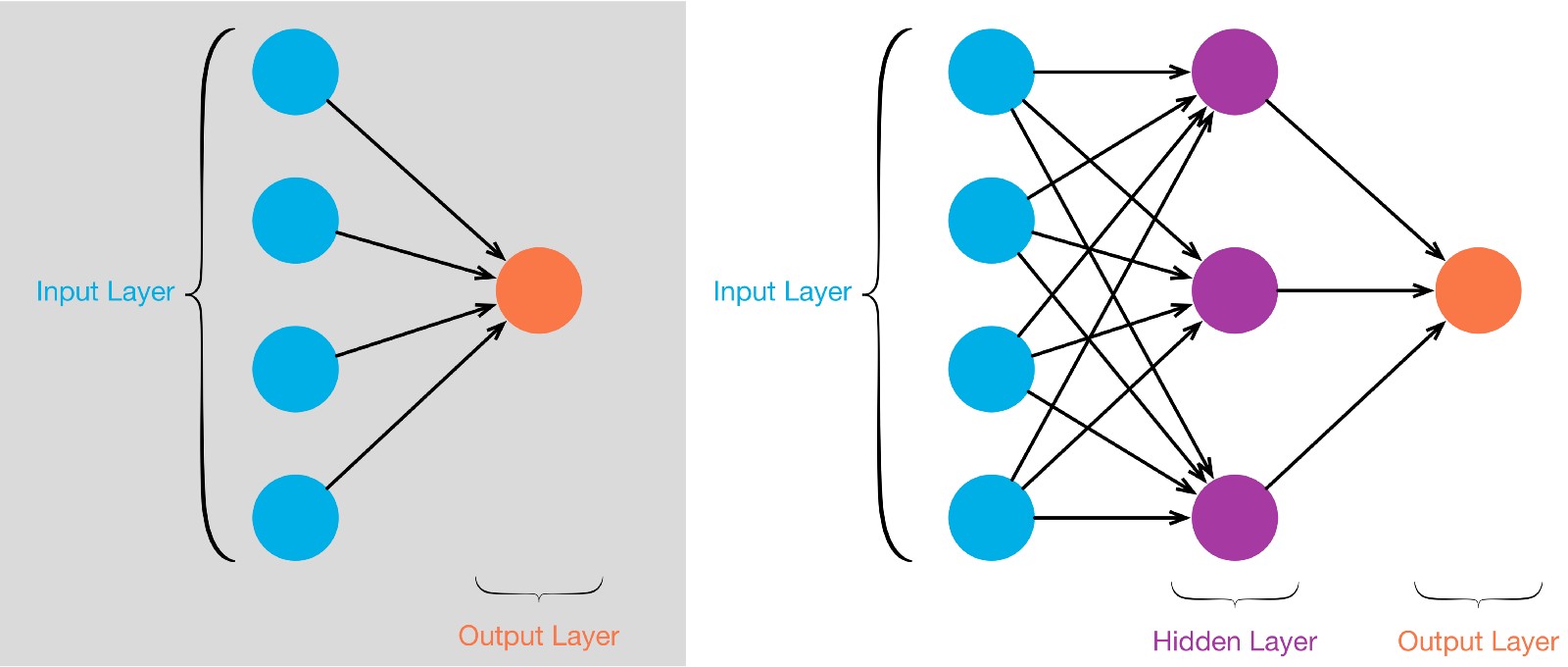
Left is a TWO LAYER network, consisting of neurons forming the input layer, and in this case a single neuron as OUTPUT LAYER taking the synapses from the input layer and do its thing with those.
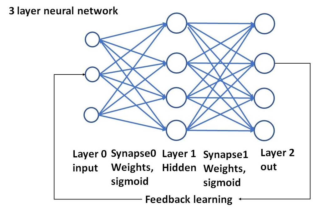
At the right a three layer network, with again an input layer and an output layer, but in between a socalled hidden layer that does its thing with the input layer synapses.
A THREE layer network can do cleverer things than a two layer network. Rember each neuron consists of the functions described above.
Ok at this stage i went back to my python 2layer neural network to clean it up for publication here.
In the program below we will work with a simple two layer network, see the picture:
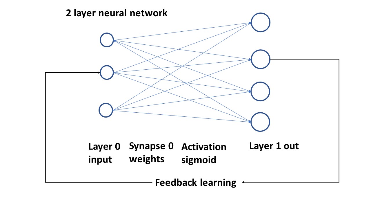
The program will do the following conform the picture:
Triple neuron input layer with values
Synapses ( weights) as array between input neurons and output neurons
The suming algorythm for the synapses will do the sigmoid activation and
generate Layer 1, which is the output
The output will be compared with a separate array and the difference (the error) will is used to change the weights.
The cycle will be repeated a large number of times and then print the last layer1 array; which will closely match the target (we hope).
Here is the program pasted raw, not yet corrected with the right indents etc. but it gives you the idea. Have a look. Next time i wil make the indents so the program is runnable, and the screendump of the output.
import numpy as np
# sigmoid function - deriv flag indicates to yield sigmoid or its derivative
def nonlin(x,deriv=False):
if(deriv==True):
return x*(1-x)
else:
return 1/(1+np.exp(-x))
# input dataset
x = np.array([ [0,0,1], [0,1,1], [1,0,1], [1,1,1] ])
# output dataset that we try to achieve
y = np.array([[0,0,1,1]]).T
# seed random numbers to make calculation
# deterministic
np.random.seed(1)
# initialize weights randomly with mean 0
syn0 = 2*np.random.random((3,1)) - 1
# set number of training iterations
for iter in range(10000):
# forward propagation, do the sums with weights ad bias
l0 = x
l1 = nonlin(np.dot(l0,syn0))
# compare result with wanted output
l1_error = y - l1
# multiply how much we missed by the
# slope = derivative of the sigmoid at the values in l1
l1_delta = l1_error * nonlin(l1,True)
# update weights
syn0 += np.dot(l0.T,l1_delta)
print ("Output After Training:")
print (l1)
print ("The actual synapse/weights for this result: ")
print (syn0)
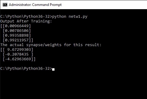
So run the program in the usual way from the command shell. The result will show after some thinking (10000 iterations!) the following.
Remember the output we wanted the program to learn was [ 0, 0, 1, 1]
The result is [0.009], 0.007], [0.993], [0.992] and this result was obtained with the synapse containing the weights:
[9.672], [-0.207], [-4.629] give or take a few more digits.
So what has happened. The program has learned itself to recognize the pattern of bits in the input x array as 0011. So if the input x was a picture (bit pattern) of a three, the program would now have learned to recognize this as a 0011 - binary 3.
So2; if we now take the synapse (weights) and use them in a much more simplified non-learning program to read the same x array, it should yield the same output.
So3; what have we achieved then is that we created a neural network (very simple) which recognizes this pattern as a 3
So4.; interesting , but if the input is a picture and not exactly the same as what we trained the network for, it will get confused. So thats a next step , you will find out when trying a real picture (see below in th robotics section).
Think about that. Thats amazing. At least, the first time i did this i found it amazing.
I will demonstrate with the following tiny program (the non learning version of the previous one) that indeed this particular x-array, combined with these weights will be recognised as representing a three.
Note that the actual result is not precisely 0011, but zeros are generally small or negative numbers, while ones are distininctly much larger.
You will find that when screwing around with the input array x and y; the result sometimes becomes unstable; a lot of combinations however are very clear and consistent.
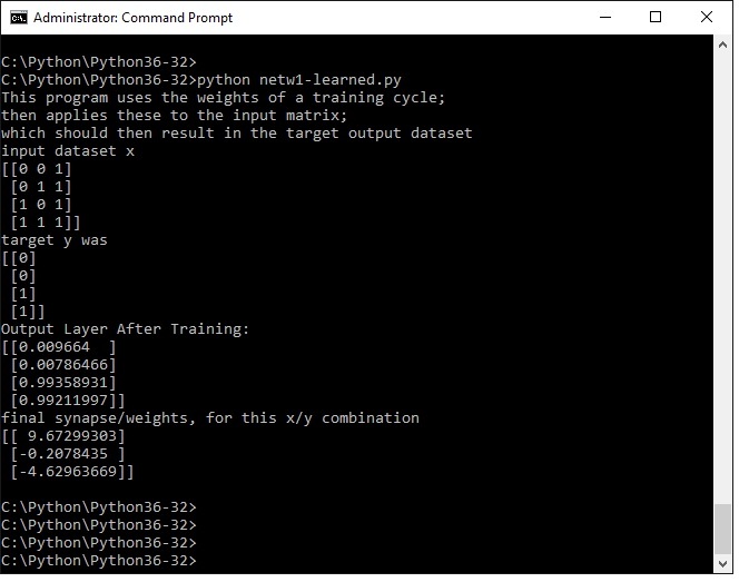
Here is the little program that takes the x input array x and applies the weights we found above in order to demonstrate that without further learning the result will be the same 0011.
print ("This program uses the weights of a training cycle;")
print ("then applies these to the input matrix;")
print ("which should then result in the target output dataset")
import numpy as np
# sigmoid function or derivative
def nonlin(x,deriv=False):
if(deriv==True):
return x*(1-x)
else:
return 1/(1+np.exp(-x))
# input dataset matrix 4x3
x = np.array([ [0,0,1], [0,1,1], [1,0,1], [1,1,1] ])
# output dataset 4x1 to be learned
y = np.array([[0,0,1,1]]).T
# initialize weights with the learned weights
syn0 = np.array( [[ 9.67299303], [-0.2078435 ], [-4.62963669]])
# forward propagation, generate output layer l1
l0 = x
l1 = nonlin(np.dot(l0,syn0))
print ("input dataset x")
print (x)
print ("target y was")
print (y)
print ("Output Layer After Training:")
print (l1)
print ("final synapse, for this x/y combination")
print (syn0)
Load and run in the same way as previous examples. The output layer l1 is clearly representing 0011
Sufficient stuff here to play around with. For example try to shorten the weights to eg. 4.62 and so on. Will work just fine.
Test by changing the input array; this will result in a nonmatch !!!!
The screendump of the command shell now will look as follows:
A 3-layer artificial neural network (ANN), going deeper
We have done the simple stuff, which should give you an idea of what a neuron can do and some background on the math used.
We ve seen that the layers are represented by l0 and syn0 for layer 1, and l1 for output.
So basically if we add the following:
l1 and syn1 and l2
we would have a 3layer network with l1 as input layer, l1 as the socalled hidden layer and l2 as output.
A 3 layer network can solve more complex things because of the extra step in between.
First lets look at the picture - i like pictures: note that i have only drawn 4 neurons un the hidden layer and 4 in the output. The program will be with 32 neurons in the hiddenlayer and 5 in the output. The principle is the same.
Programwise the expansion from a two layer to a three layer network is not extremely difficult if we understand the 2 layer version. Its about adding the input arrays, and syn1 handling.
The program as shown below will have the following matrices during its runtime:
(Matrix is shown as row x column)
1. Input l0 (=x) : 6x5 matrix
2. Syn0 : 5x64
3. L1 layer is the result of (l0.syn0) : 6 x 64
4. Syn1 : 64 x 1
5. Output l2 is the result of (l1.syn1) = 6 x 1
Understanding this and getting it to run, its not very difficult to use a larger input matrix, e.g. 12 x 10 and see what happens.
But first the program with a 6 by 5 matrix
# 3 Layer Neural Network:
# with variable hidden layer size
import numpy as np
hiddenSize = 32
# sigmoid and derivative function
def nonlin(x,deriv=False):
if(deriv==True):
return x*(1-x)
else:
return 1/(1+np.exp(-x))
# input dataset format 6 rows x 5 columns
X = np.array([
\ [0,1,1,0,0],
\ [1,0,0,1,0],
\ [0,0,1,0,0],
\ [0,1,0,0,0],
\ [1,0,0,0,0],
\ [1,1,1,1,1]])
# output dataset 6 rows x 1 column
y = np.array([[0],[0],[0],[0],[1],[0]])
# seed random numbers
np.random.seed(1)
# randomly initialize our weights with mean 0
syn0 = 2*np.random.random((5,hiddenSize)) - 1
syn1 = 2*np.random.random((hiddenSize,1)) - 1
# now learn
for j in range(60000):
# Feed forward through layers 0, 1, and 2
l0 = X
l1 = nonlin(np.dot(l0,syn0))
l2 = nonlin(np.dot(l1,syn1))
# how much did we miss the target value?
l2_error = y - l2
# if (j% 10000) == 0:
# print ("Error:" + str(np.mean(np.abs(l2_error)))
# in what direction is the target value?
l2_delta = l2_error*nonlin(l2,deriv=True)
# how much did each l1 value contribute to the l2 error (according to the weights)?
l1_error = l2_delta.dot(syn1.T)
# in what direction is the target l1?
# were we really sure? if so, don't change too much.
l1_delta = l1_error * nonlin(l1,deriv=True)
syn1 += l1.T.dot(l2_delta)
syn0 += l0.T.dot(l1_delta)
# to use the learned weights separately we need to save l1 and l2
# (syn0 and syn1)
print ("input matrix is: ")
print (X)
print ("output after training: ")
print (l2)
print ("output needed was")
print (y)
The input matrix vaguely resembles a digit 2 (as far as possible with a 6x5 matrix), the output y to be achieved i have set as 00010; which would be binary 2; it can also be seen as the second bit from the right (i will come back to that issue later).
Now all the program has to do is to recognize the input matrix as a 2; lets see what the command shell says:
Hm .....
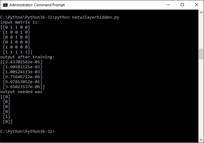
These numbers may seem a bit mysterious, but they are in scientific notation.
This is m*10 to the power of n. If n is a negative number you could actually say m / 10 to the power of n. A negative exponent means actual divided by.
So the larger n is , the smaller the number, QED.
One number is clearly a lot larger than the others by virtue of the number being to the power of e-01; the second largest is e-03.
Thats a lot smaller
So yes, eureka, indeed , the program has recognized the input quasi picture 2 and linked it to the number 2.
Now play around with different input matrices and output matrices and see where the program will fail. I would set the number of iterations at 60.000 or less (try), thats a lot faster.
You can also play with hiddenSize and see where the program dies.
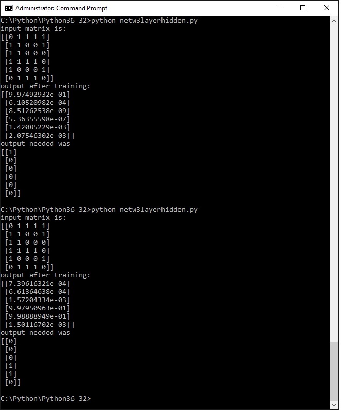
The following screendump i did with a digit 6 (of sorts) and two different ways of output. The first one where the 6th bit corresponds with the input nr. 6. The second one with binary six (110) corresponduing wit the input number.
In general the method with one bit works best. You will also see that the quality of the input determines a correct output, try it.
In the case of this input matrix both versions yielded a correct output - need more study to research why and if this can be made consistent.
I will make a version with input matrix 12 x 10 and output 10x 1 , and do the full set of digits from 0 to 9, with a single bit out of 10 output., where the 0 (zero ) should give bit 10. Probably its best to raise the hiddenSize to 64. We'll see.
Next come the results of a larger matrix representing digits 0 t0 9. Is it consistent?
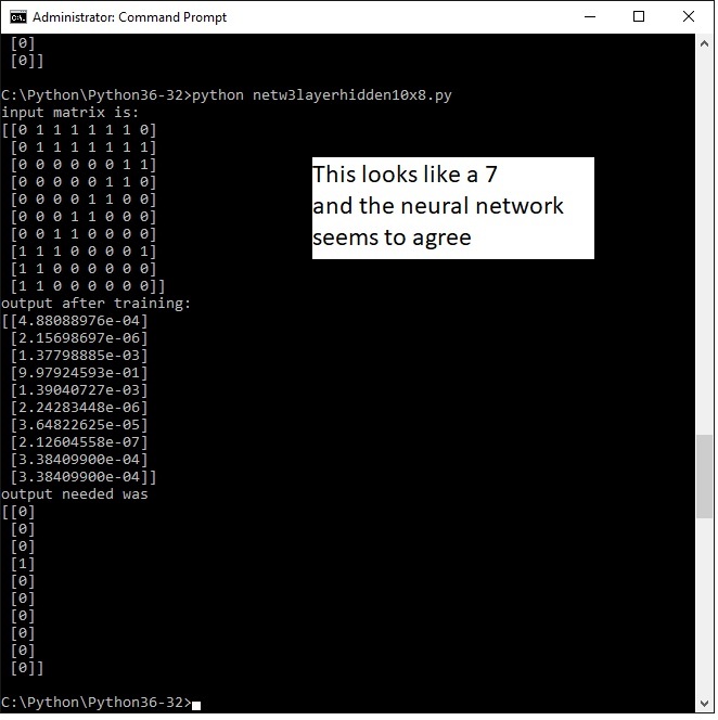
TEN by TWELVE ARRAY INPUT RESULTS
Below the results of the same program , but with a larger input array of 10 by 12 . It still is a toy application so its probably not very scalable to very large arrays for example those that would represent an image with greyscale pixel values. The output is 10 wide where each postion represents a the number so from 1,2 ,3 ,4 ...... to 9, 0.
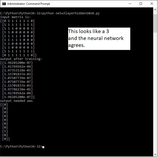
Actually the three is mirrored. That shows we can teach the ANN to see the mirrored three as a ..... 3.
I won' t place all the runs on this page. I however did some more runs and for now its performing fairly consistent with this matrix size..
Next step is to get a more powerful routine and try it with publicly available image data bases freely available on the net.
But first i am fascinated by the next subject, reinforcement learning.
Reinforcement learning with BB8 - into robotics - failed start!
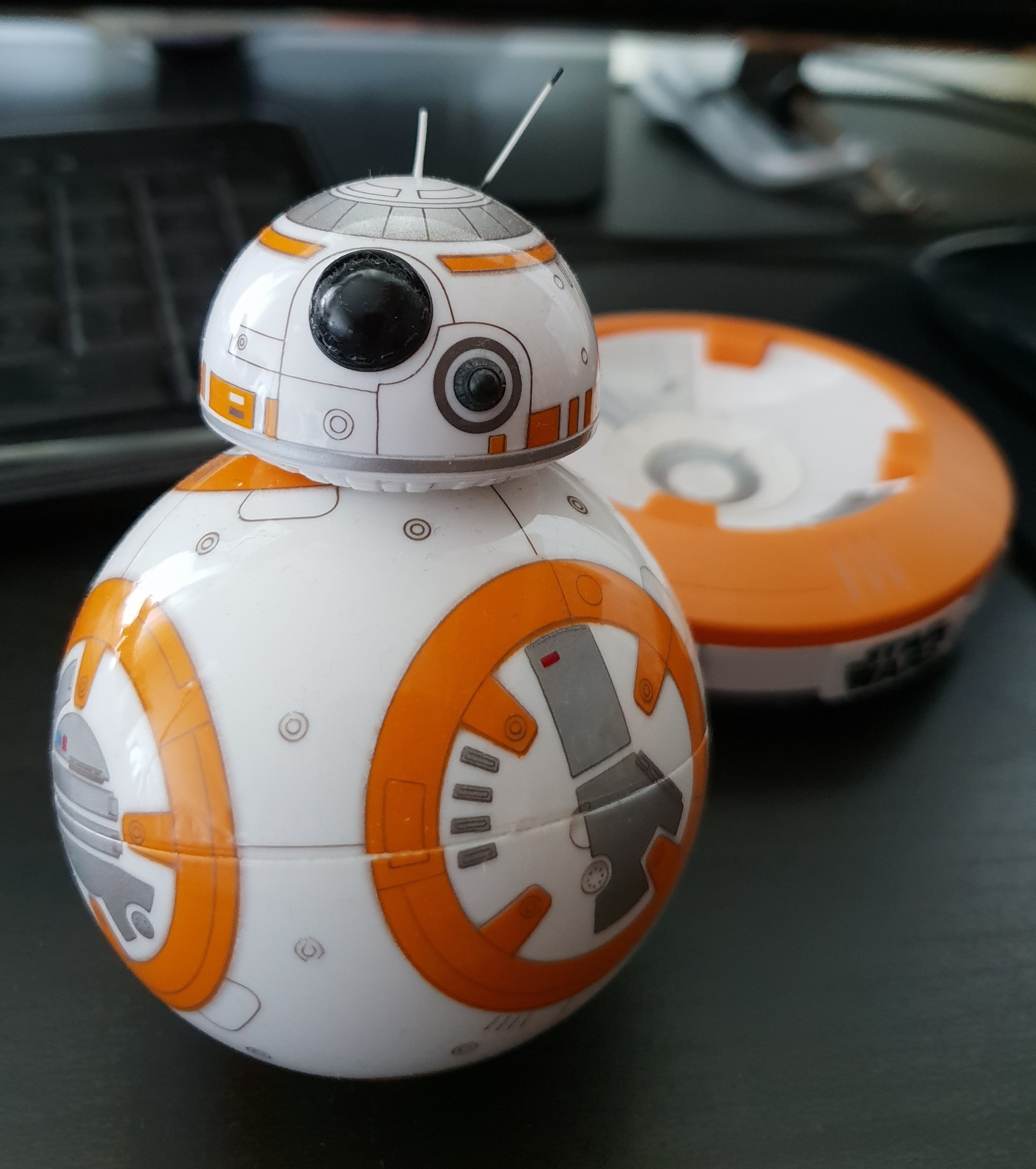
I decided to take you (and myself) on a more ambitious adventure. The plan was to take BB8, which can be programmed by javascript and adapt the QLearning routines i found such that BB8 will learn by itself to find a path through a room or maze, with no previous information.
This is different from the previous neural network exercises that learned from examples and a required output. This is also a bit harder, a large number of bits harder, megabits actually.
After some research i abandoned the BB8 path. Its sensors and their lack of acuracy make this too complex. BB8 is just a charming toy, lets accept that.
So presently am studying reinforcement learning and thinking about something creative i might do with it. With minimum investment of course.
See the next step below.
It would have been nice.
.
Reinforcement learning plus ANN - exercise into robotics
A robot is a mechanical entity that can move through the world without external controls -an automaton.
It seems that the best approach is to focus on Reinforcement Learning and buid a tiny and simple model as proof of concept./
I have chosen the Raspberry zero for the robot as its extremely lowcost. and very complete with the latest version of Python and wide support of inputs and outputs.
If this works on the zero , it will work on almost anything.
The Python software modules to be developed
1. ON a PC :
The 3layer neural network will run on the PC in order to train the network recognizing a limited number of pictures. For now i am using my old I3 desktop. A next step will be to get a PC with an NVIDIA GPU which will speed up the matrix operations. dramatically.
The Raspi zero (single core) is too light to do this.
The ANN will producte for each picture a set of synapses and the code (4 bit binary) which represents the picture.
The synapses of a all pictures are stored in a folder called synapses which basically represents the memory of the Neurons.
The folder with the synapses will be transferred to the Raspi
The procedure is to first train the network on basis of a number of pics and permutations , to store the synapses.
This part works ok and i will publish the scripts lateron.
2. ON the Raspberry Pi zero:
The necessary drivers for the Picamera and Python scripts to preprocess a .jpg picture of what the robot "sees" to a 100x100 array that can be loaded into a numpy array.
The robot will frequently take a shot (a still) with the Picamera and submit it to the preprocessing script.
A subset of the 3layer ANN above. It will do only one iteration of the sigmoid code based on the 100x100 array representing the picture of the world in front of the robot, in combination with the synapses of the known pictures above.
For each known picture there is a set of synapses , so this script will loop through the set of stored synapses until it hits one with the same binary result . After a lot of hassle and headachte this works fine.
That represents the picture the robot sees in front of it and based on that the Markov routines can take decisions (go right, left, stop or take a reward)
Next to be developed to run on the Raspi is a set of Markov routines to map out the environment and then find an optimum way through a maze or similar. This is not yet ready., socalled WIP.
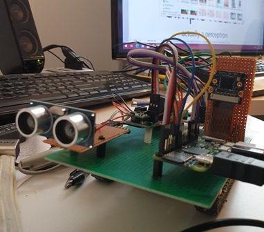
Hardware and python drivers for the hardware(being on my own this had to be ultra-lowcost)/
a. to control the Raspberry for initial developement you add a USB keyboard plus mouse (need a usb multiple gate), and mini HDMI to normal HDMI cable to get the display on a monitor or TV.
Moving software from your PC to the Raspi is easy with WIN SCP, a ftp app.
controlling a free roaming robot from your PC (on the same wifi network) use csv (user pi, add the ip address and DO CHANGE the standard password) in the command prompt.
b. a motorized and steerable platform. I am using a thingy called Minirover which has two motors on board, driving tank like caterpillars. And its fairly cheap.
A quadruped thingy would be nicer, but from the pov of doing a an AI exercise this is not relevant, only much more expensive.
c. some computing power. I am using the Raspberry Pi zero, cheap, which has wifi and a lot of connectivity on board, as well as a good Linux based OS and a lot of useful software packages.
I use the Raspberry with power by external usb supply, HDMI to an old TV, and USB to connect mouse and keyboard. No problem there. Make sure you get a set of testcables.
NOTE: when you have some sofware running on it, it needs to be able to roam freely, i.e. without cables. You can (on the same WIFI) network get a command shell in order to start and stop the scripts.
d. You need hardware and software to drive your two little engines. The L298N dual DC motor drives works great and drivers are easy to find (see below)
e. A robot needs some sensory input. I have chosen an the ultrasonic device, which gives you an accurate reading in cms. distance from an object or wall. I use the HC SR04 ranging module. See sample script below.
f. I added a second sensor, the PICamera. Connecting is a nobrainer, you only need a special flatcable for Raspberry, as the camere comes most cases with a cable for the Arduino.. In order to use it you need image processing software, a small neural network so that the little robot can actually see what its running into. The ultransonic device will only tell it there is something.
g. some powersupply to get the 3.3V needed for the RP. All standard kit.. You need to add lateron batteries (rechargeable) to drive the two DC motors and to provide the power for the logic. The Raspberry world comes with a nice tiny converter board (battborg) taking anything upto 35V to produce power for the logic.
For testing i have placed the robot on a box with the caterpillars off the ground so you can test with all the cables in.
The total cost for the above doesnt have to be more than 100 USD slightly less in Euro.
.
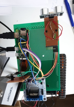
Wiring the distance sensor and motordriver and Picamera to the Raspberry Pi
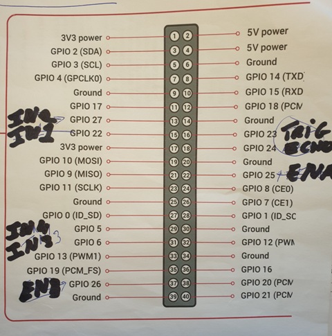
The heart of the robot will be the Raspberry PI (in my case the Zero WH). The Raspi communicates with the world through a 40 pin connector. numbered 1 to 40. Behind that are the GPIO definitions allocated to the physical pins. Your software will talk to GPIO numbers, the wires of the sensors will connect to the little physical pins. Dont ask why, it is as it is..
It is useful to make a note like below as to which pins the wires are connected.
The L298N dual DC motordriver connects to GPIO 27, 22 and 25 for one motor, and Gpio 5,6 and 26 for the other. You also need to create a common ground by connecting the ground from the L298N to pin 6. Thats all. You need to give the L298N its own power, in my case i used a 9 V rechargeable.
NOTE: i quickly found out that these batteries carry to litttle power. I will have to revert to a set of 8 AAA batteries that carry at least something like 2000 mAh.
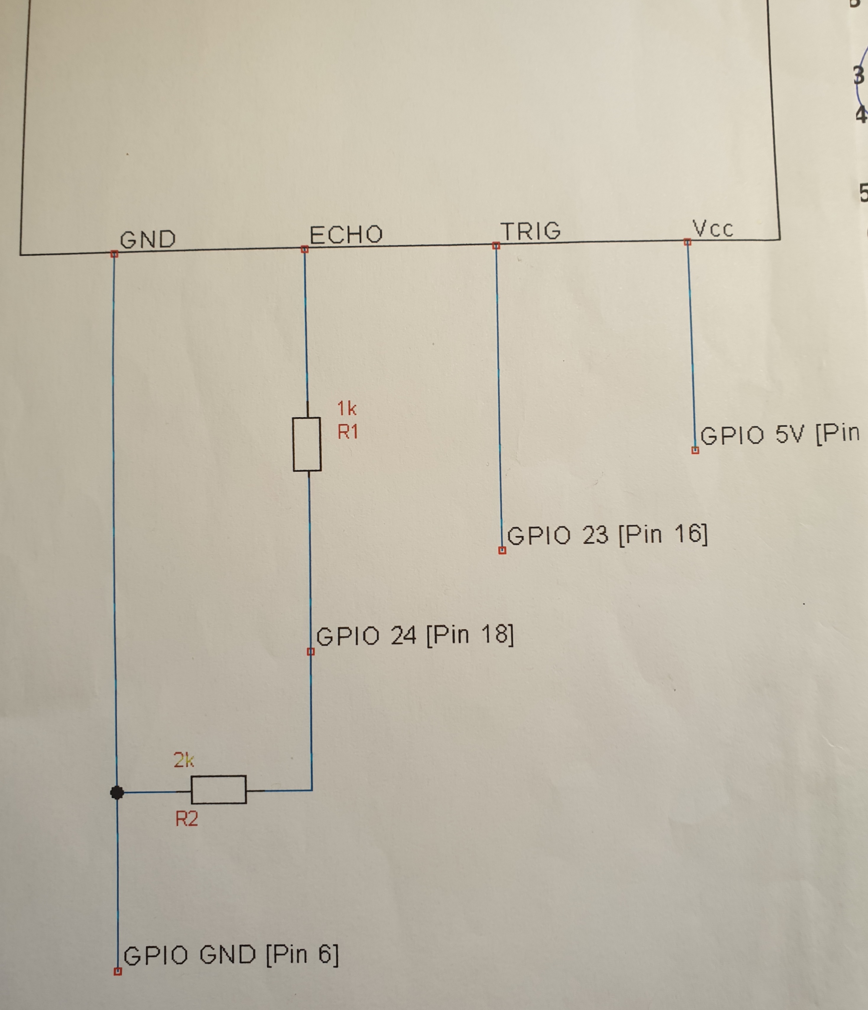
The Ultransonic device HCSR04 needs a bit more work, must be mounted on a bit of pcb and a little bit of wiring (see below), but than connects to GPIO 23,24. One lead is te trigger, the other lead receives back the echo. The scrips calculate the distance on basis of the elapsed time between trigger and echo., The input signal of 5 volt needs to be brought back to the Raspi's 3.3 volt, hence a bit of wiring with two additiona resistors of 1k and 2k (roughly) in order to create a voltage divider (Google that one if you want to know how it works).. If you do the wiring below you end up with a little circuit with a 5V, GND connection (can be connected to any 5V or Ground pin) and a Trigger and an Echo connection going go GPIO 23 and 24.
The Picamera is an nobrainer. You need the camera with the correct flatcable for you Raspi. Connecting is using the dedicatd connector on the Raspi board. Look up the raspi wbsite how to. The little connector is very tiny, very vulnerable and i of course fucked it up. Managed to connect it but dont ask me how.
Thats all folks. You now have a platform with two motors, that can sense distance and see the world.
.
Feeding the little beast, logic circuits and motors
We want to feed the beast with a source for the logic , the 5V necessary for the Raspi and other logic circuits, and you need a source to feed the motordriver and the motors separately.
Firstly, I used the battborg for the logic. A tiny board that takes 9 volts DC in and will provide 5 V to the logic.. A standard 9 volt battery will run for hours.
Secondly, I have a holder for 8 x kk1.2 volt AA batteries, which are available in higher capacity for the driver board plus engines. A standard 9 volt battery will go dead in 10 minutes or so.
Any surges from the cheap motors are thus kept away from your logic.
Python software scripts for the sensors and motordriver
A. You need Python and some programming experience. Python comes on board of the Raspberry pi , available on a microSD card with all kinds of packages for our purpose.. See the imports in the examples below.
B . Interrupts.. In order to have the endproduct run smoothly in realtime, i need to figure out the interrupt system on the Raspi to allow realtime functioning.. I havent figured that out yet. For now i will run each script, pause and then run the next script.
I will run each module : check for obstacle, , turn left or right, check obstacle, if no obstacle go forward , repeat. Not elegant., but ok for a proof of concept., and it works. Just for the heck of it i added small clip at the bottom.
C. You need drivers to trigger the ultrasonic device and a script function to calculate the distance from a possible object. Here is a script that will give you a distance in centimeters from any object ahead.
NOTE: once you have the GPIO tool and picamera tool , you can onlly run the scrips on the Raspberry of course.
NOTE; in case you use the scripts below, you need to add the indents. Python is very sad if you fuck the indents up.
In the robot script i will use it to see if an object is more than 10cms away or less. If more you can go forward a bit, if less you have to turn left or right.
first import the below list of tools:
import numpy as np
import picamera
import RPi.GPIO as GPIO
import time
import random
from time import sleep
# where am i, measure distance must be a function definition #
def distance():
GPIO.output(TRIG, False)
print ("waiting for sensor to settle")
time.sleep(2)
GPIO.output(TRIG, True)
time.sleep(0.00001)
GPIO.output(TRIG, False)
while GPIO.input (ECHO)==0:
pulse_start = time.time()
while GPIO.input(ECHO)==1:
pulse_end=time.time()
pulse_duration = pulse_end - pulse_start
distance = pulse_duration * 17150
distance = round(distance, 2)
print ("Distance ",distance)
return distance
You call it by :
d=distance()
if d>10: #that direction is empty space go there and update the world matrix
move=forward() #physically in our last direction
etc.
D. drivers for the DC motor interface, allowing to go forward, backward, left, right and stop. No problem.
Here is a snippet of python code to handle the L298N dual DC motor interface: You have to connect the L298 points to the correct GPIO points. on the Raspberry. For example here in1 of the interface connects to pin 15 of the Raspi, which is GPIO 22. The site raspberry.org provides more info.. Once you have all the little cables connected the follow Python code makes sense.
# first import the necessary packages for the motordriver
import RPi.GPIO as GPIO
import time
from time import sleep
# motor driver definitions #
# right motor
in1 = 22
in2 = 27
en = 25
temp1=1
#left motor
in3 = 6
in4 = 5
enb = 26
temp2=1
GPIO.setmode(GPIO.BCM)
GPIO.setup(in1,GPIO.OUT)
GPIO.setup(in2,GPIO.OUT)
GPIO.setup(en,GPIO.OUT)
GPIO.output(in1,GPIO.LOW)
GPIO.output(in2,GPIO.LOW)
p=GPIO.PWM(en,1000)
p.start(25)
GPIO.setmode(GPIO.BCM)
GPIO.setup(in3,GPIO.OUT)
GPIO.setup(in4,GPIO.OUT)
GPIO.setup(enb,GPIO.OUT)
GPIO.output(in3,GPIO.LOW)
GPIO.output(in4,GPIO.LOW)
q=GPIO.PWM(enb,1000)
q.start(25)
#function move forward one second by running the motors , back, left, right are more of the same#
def forward():
GPIO.output(in1,GPIO.LOW)
GPIO.output(in2,GPIO.HIGH)
GPIO.output(in3,GPIO.LOW)
GPIO.output(in4,GPIO.HIGH)
time.sleep(1)
print("stop")
GPIO.output(in1,GPIO.LOW)
GPIO.output(in2,GPIO.LOW)
GPIO.output(in3,GPIO.LOW)
GPIO.output(in4,GPIO.LOW)
#call the function as follows
x=forward()
E. Support for the Picamera is included in the Python packages,, providing support to take stills. I plan to take stills at intervals and to analyze these for a particular picture. In order to read the stills
#using picamera to capture a still of what is ahead. Must be optimized and also rewritten as a function.
import picamera
import RPi.GPIO as GPIO
import time
from time import sleep
from picamera import PiCamera
camera=PiCamera()
camera.start_preview()
sleep(5)
camera.capture("world.jpg")
camera.stop_preview()
If you still have a monitor attached to the Raspi, you will see the preview for 5 seconds. After it you will find the picutre world.jpg or a name of your own chosing in the directory Python runs in.
F In order to use the stills as input for the RL or NN routines we need find some routines to a. reduce the size of world.jpg ; eliminate background. The stills are too much data, much more than needed for our purpose.. Some scripts for image processing follow here. I have scripts to reduce the size, to convert to bpm, to convert to b/w.. to load the result into a workable numpy array.
See below
This all works nicely. .
Now it all needs to be integrated with the ANN and RL routines., into one robot application.
The RL and ANN vision routines:
This is still (a lot of ) work and research in progress.
I need to design:
a. a simple real life maze or route, for the robot to learn., 8 x 8 seems to work for proof of concept., and how to represent the world in that matrix
b. python routines to pre-process the stills from the camera, using image processing to convert the fairly large world.jpg into a fairly small black and white world.bpm . Working on a variation of one of the Neural Networks above to recognize 4 different simple pictures.
For starters i made an image preprocess script that will take any picture here called arrow2.jpg and create a 100 by 100 black and white .bmp image (i.e. one bit per pixel.), so that the neural network doesnt become to complex. Here the preprocessing script (can be cleaned up, as it contains a lot of in betweens for testing):
# preprocess world.jpg from picamere. scale down, make bmp, convert to bw, array
from PIL import Image
import numpy as np
#scale down the image#
img = Image.open('arrow2.jpg')
new_img = img.resize((100,100), Image.ANTIALIAS)
quality_val = 90 ##you can vary it considering the tradeoff for quality vs performance
new_img.save("arrow2-resized.jpg", "JPEG", quality=quality_val)
#convert resized image from jpg to bmp#
img = Image.open('arrow2-resized.jpg')
ary = np.array(img)
# Split the three channels
r,g,b = np.split(ary,3,axis=2)
r=r.reshape(-1)
g=r.reshape(-1)
b=r.reshape(-1)
# Standard RGB to grayscale
bitmap = list(map(lambda x: 0.299*x[0]+0.587*x[1]+0.114*x[2],
zip(r,g,b)))
bitmap = np.array(bitmap).reshape([ary.shape[0], ary.shape[1]])
bitmap = np.dot((bitmap > 128).astype(float),255)
im = Image.fromarray(bitmap.astype(np.uint8))
im.save('arrow2-resized.bmp')
#now convert world to pure b and w#
img = Image.open('arrow2-resized.bmp')
thresh = 200
fn = lambda x : 255 if x > thresh else 0
r = img.convert('L').point(fn, mode='1')
r.save('arrow2-bw.bmp')
#load world into a np array LATER
#im = Image.open("arrow2-bw.bmp")
#p = np.array(im)
#print (p)
The last four lines can be used in the main program to load the 100by100 image into numpy array for use by the neural network
We only need to recognize three or four different images in our little world., for example an arrow left, an arrow right and a picture of a reward (for Markov RL)
Currently i am stuck, to be honest, in the neural network. I can recognize a single version of a picture (for example an arrow). However as the robot moves it will see the arrow with Picamera, but not aways in the same way. Distance may be different, angle of approach may be different. The neural network will have to recognize it as an arrow irrrespective.
I did a test script with the 3layer ANN on the PC, using the OPENCV to remove background noise from the images. That worked perfectly. The ANN recognized the arrows from different perspectives without fail. Regretfully OPENCV on the Raspberry zero is a nogo, very difficult to install and likely to kill the Raspi performance. I could go to the multi core Raspberries but they are much more expensive, no fun. So, for now i am searching for a Python script with a light footprint that will remove the backgrond from an image
c.. A script/function to explore the maze and fill in the possible states. into a matrix R. Currently the robot as it is starts with all cells in the matrix at -1, meaning unexplored, a cell i can go to will be set at 0, and a cell that is blocked will be set at 1. For testing the world consists of 100 cells, 10 by 10 matrix.
d. RL algorythm (Markov) to learn about the maze and find the best way through without supervision, after exploration is complete. The idea is that the robot can be placed at startcell and find the fastest way to the cell with a high bonus. Here that cell would be represented by a wall with an arrow picture.
Currently the robot works on basis of the ultransonic only. On start it will check if there is an object closer than 10cm ahead, if not it goes forward and checks, if there is blockade it will try to turn right or left and check, and move accordingly. All the time updating the cells it sees with either 0 or 1.
Not very impressive, but its already a lot of work to figure out all that basic stuff.
Different approach 2022. A small 3 x 5 x 4 ANN running on Arduino Nano + OTTO.
Trying to get the large ANN plus image processing running on the Pi zero , i very clearly hit the limits of the PI zero (for example forget OpenCV, nogo).
Recently i ran into the OTTO DIY walking robot (a fun little thingy), which is driven by Arduino Nano. All very lowcost.
I managed to get a tiny ANN running on the Nano. Neural configuration 3 neuron input, 5 neuron hidden, and 4 neuron output layer.
If you use the sonar distance capability of the OTTO to measure distance to some object ahead, left and to the right, (3 input layer), then the neural network can learn to go ahead, back , left or right. Now obviously this is a bit of taking an elephant to kill a cockroach, BUT as proof of concept its brilliant. AND IT DOES WORK.
You write everything your self in C++ (Arduino IDE) in very basic code (no matrix math for example), in doing this the innerworkings of the ANN become much more clear.
I took the following discrete steps:
0. Bought the crazy cheap X1 3d printer to print the rotating head parts, available for free from the OTTO DIY site.
1. Build the OTTO DIY robot with the rotating head expansion. This allow you to take three (or more if you wish) distance measurements.
2. Downloaded the example C++ ANN sketch for Arduino from Hobbyzine robotics page, and tested. Ok in one try.
3. Modified this into two parts :
a. the training module ( the Hobbyzine sketch slightly modified).
b. a slimmed down second module (sketch) that takes the trained weights and runs them once to produce the 4 required outputs. This is the 'walking' module.
c. testing the walking module with a separate Arduino with only the sonar attached.
4. compile and upload into the OTTO and let it go.. Bingo.
5 cleanup the ANN sketches for publishing on this site.
Note: the training module prints the resulting weights on the serial arduino. These are the hidden weights and the output weights. These two small arrays are easily copied/paste manually
into arrays in the walking module sketch as they are small. Better would be to have to two arduinos communicate, but thats for later.
It does actually work, but i need to improve the servo performance for the head (cheap SG90) and i need to cleanup the training and walking sketches from all kinds of debugging stuff.
(software and pics will follow asap)
Pausing for a while feb 20/22 - time passes .....
Improving the OTTO servo performance .............
Be back.